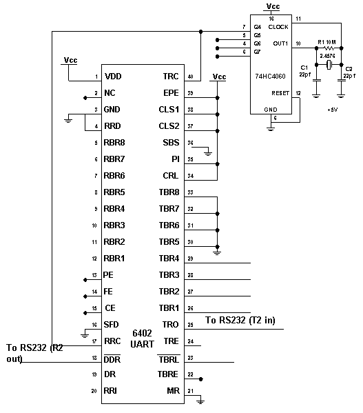
4. Receive /Transmit control on UART

Fig.
4 Illustration
of UART on Receive and Transmit control
4.1 Initialization and
Controls
The UART requires a clock input, 16 times greater than the Baud Rate it uses. This is generated by the 74HC4060, 14 bit binary counter/divider. With a 2.4576 Mhz crystal, the frequency at Q4 (Pin 7) is 153.6 Khz. When divided by 16, it gives 9600 BPS, thus this the transmission speed. The other Communications Parameters are set by the CDP6402's Control Register.
The Control Register Consists of Parity Inhibit (PI), Stop Bit Select (SBS), Character Length Select (CLS1 and 2) and Even Parity Enable (EPE). These inputs are tied high in this application but these pins can be atched using the Control Register Load (CRL). changes made to these pins will immediately take effect. The Current Configuration is 8N1, i.e. 8 Data Bits, No Parity and 1 Stop Bit.