![]()
![]()
4.2
Transmitter Operation
The
transmitter section accepts parallel data, formats it, and transmits it in
serial form (Figure 5) on the TRO terminal.. D4
to D7 are not used as the input number formatted to a nibble thus using 4
LSBs.
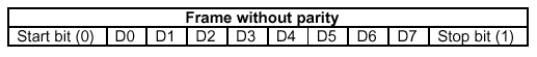
Fig.
5 Illustration
of bit format of Transmit bit format
Transmitter
timing is shown in Figure 6. (A) Data is loaded into the transmitter buffer
register from the inputs TBR1 through TBR4 by a logic low on the TBRL input.
Valid data must be present at least tDT prior to, and
tTD following, the rising edge of TBRL. Since 4-bits are used,
only the least significant bits are used. The character is right justi-fied into
the least significant bit, TBR1. (B) The rising edge of TBRL clears TBRE. 1/2 to
11/2 cycles later, depending on when the TBRL pulse occurs with respect to TRC,
data is transferred to the transmitter register and TRE is cleared. TBRE is set
to a logic High one cycle after that.
Output
data is clocked by TRC. The clock rate is 16 times the data rate. (C) A second
pulse on TBRL loads data into the
transmitter buffer register. Data transfer to the transmitter register is
delayed until transmission of the current character is complete. (D) Data is
automatically transferred to the transmitter register and transmission of that
character begins.
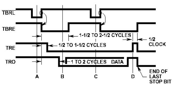
Fig.
6 Transmitter
timing diagram