![]()
![]()
9. ITDL Front panel connectors, Accessories and Physical dimensions
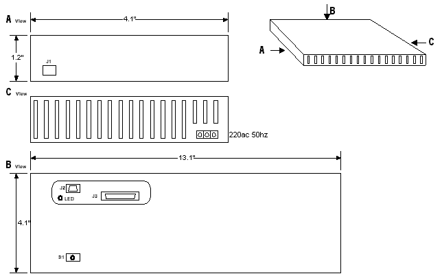
Fig.
6 ITDL physical layout and dimensions in 3
planes
Power
socket mounted on the right hand bottom side of the back panel of the ITDL (C
view)
S1
– Reset switch. This is mounted on the PCB and a screwdriver or pointing
device should be inserted to press and reset. This is to prevent ITDL from
resetting accidentally (B view).
LED
– Continuous blinking of this LED indicates that RAM contents are being
successfully downloaded to the computer.
J1
– This RJ type connector provides the telephone line interface in parallel to
ITDL.
J2
– 9 pin serial port to facilitate the interfacing between ITDL and computer.
J3
– 25 pin printer port (10 to 25 conversion associated to ITDL). This is used
to link the ITDL with printer.