![]()
![]()
3. Polarity reversal and interrupt handling
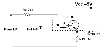
Fig.
3 Polarity
reversal detecting circuit
The circuit is used to monitor the polarity changes, which occur at the input terminals at the moment of both party call establishment. Therefore, it is important to request the polarity reversal facility and get the approval to fix ITDL in parallel to TP line from the respective regional branch of the Telecommunication Company.
The
opto-isolator SFH610 ensures complete isolation between –48V and ITDL. With
the system connected to TP line and during the time –48V appears at A, current
1mA flows through the LED in the opto-isolator. The associate transistor then
conducts and logic ‘1’ appears on the emitter. At the moment of call
establishment, polarity reverses and opto-isolator LED ceases conducting thus
appearing logic ‘0’ at the emitter to interrupt Z80.