6. Printer interfacing
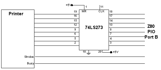
For the purpose of printing the information stored in RAMs and in turn to connect ITDL to a printer, a printer interface is associated to the system through Port B of Z80. In order to minimize the size of the connector and subsequently to reduce the PCB layout, a 10 pin connector is mounted on the PCB. This needs a conversion arrangement to inter-link PCB connector and printer connector as shown below.
PCB connector Printer Connector
GND
Connector body
GND
Pins 19 to 25 Data
Pins 3 to 10
Data
Pins 2 to 9
Busy Pin 1 Busy Pin 11
Strobe Pin 2 Strobe Pin 1

Fig. 4 Illustration
of printer interfacing to ITDL
At the end of the month user can connect his printer to ITDL printer port. As the printer is switched on, Z80 checks whether the printer is ready for printing and consequently relay the information stored in RAMs. Printing commands and the printer format are governed by a subroutine in the main program. A sample printing is shown in Table 2. At the end of the printing user can reset ITDL by pressing “Reset” switch and subsequently the entire RAM contents will be erased. Otherwise RAM contents will remain unaltered as long as the existence of power and might get crowded, from the new arrival of call information during the operation of successive months. If the number of calls does not exceed 200 to 300 within a period of one month, ITDL can withstand a capacity of two months data.
T/P
No.
Date/Time (dd mm yy Hrs.)
Duration (min. sec.)
071758248
01:08:99.13:22:59
12.29
957241
01:08:99.15:52:23
5.49
074215234
02:08:99.08:29:12
23.19
433203
02:08.99.10:05.39
4.13
433203
02:08.99.10:15.31
2.38
252861
04:08.99.22:05.43
14.54
958368
05:08.99.00:56.11
2.11
234286
06:08.99.09:12.53
23.32
Table
2 A sample
printout of detailed listing of ITDL